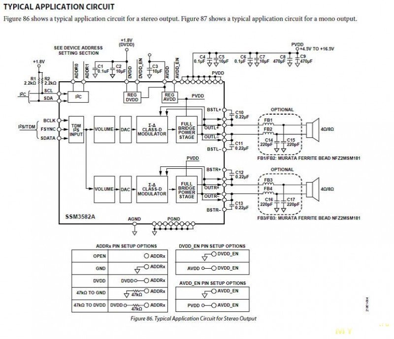
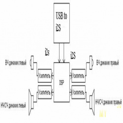
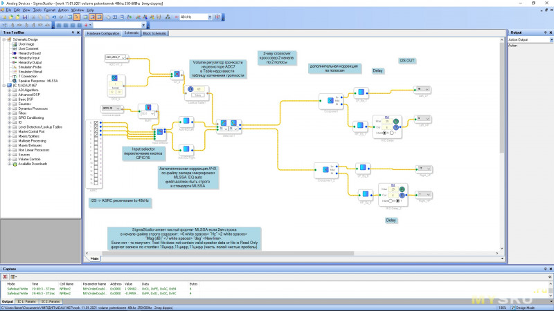
There is an automatic correction module for the MLSSA file. Here it is very nice to tune each band on the microphone “on the go” without recording to a USB flash drive – just measure on the fly, insert a filter and align everything. Chinese boards have LDO stubs on board. There are also a bunch of programmable GPIOs in case 4 standard i2s are not enough If you sweat a lot, then you can adjust the correction on FIR filters that do not twist the phase. Information in Russian on how to set up the system in Sigmastudio is sooooo scarce, and if you don’t have English without a dictionary, then it’s very difficult to understand. Maximum sampling rate – 192 kHz There is no voltage regulator on the Chip-Dip board to reduce the cost, and the DSP operates from 3.3 volts. The most popular DIY processor is the ADAU1701. link 2. Intensifying modules. Two speakers play the same frequencies in the crossover zone. Project scheme: I scored on such support and installed SA9023 – everything worked as it should from half a kick. But it turned out to be much more accurate to do everything by hand. But unlike the first act, this project can be repeated by any sufferer. The input selector module is switched by one button on the universal input/output pin GPIO16/ This is the second part of the Marlezon ballet about a two-band shelf speaker. The block has an ASRC module and the input audio stream of audio data can be resampled to the DSP frequency on the fly. Delay module for RF channel. It will probably be a separate epic. Direction to i2S exit. BUT MCLK should remain alone, because it is, in fact, a clock generator for the DSP. Two-band crossover – here we set the number of bands, crossover frequencies, the difference in the level of the bands, and the type and slope of the cutoff filter. Works the same way https://jiji.ng/victoria-island/55-safety-boots. My first experience with DSP was when setting up a fancy 3-lane project using a Berringer DCX2496 processor. DSPO link – a convenient i2s connection scarf – a connector with its own 12.288 MHz quartz oscillator with buffering and its own 5V power supply. I’ll tell you about SSM3582A separately/ Frequency response correction on filters for each band. The main problems are a frail ADC at the input and hiss in the sound. Therefore, I had to buy RDC1-0028, Double DC-DC. 2. 3. And there are a lot of settings inside.
link If there is no 3.3 volt power supply in the comb at the i2s input, then it supplies its clock, and if there is, it conducts what comes from USB. Switching to 96 is hypothetically possible, but you need to change the firmware with the controller and, in theory, also reconfigure the clock generator. Essentially, the DSP is switching to using its own oscillator rather than taking the masterclock from the i2s input, this is set in SigmaStudio. 2. 4 Or put quartz on the board and clock everything from it. 1. And if they have a phase shift, there will be a surge in the PFC and there will be nothing good to hear in this zone of joint sound. It’s the easiest to use. Digital inputs (I2S) – 4
1. The two variants of XMOS converters also play without problems.  Auxiliary ADC AUX channels – 8 I have a bunch of converters – took it and forgot the problem. I2C and SPI control interfaces (master or slave) 5. link 3. The Kenwood LS-11EX speaker systems on the Davis KVK 130 fit the mood and generally made the acoustics different. This one also works fine without problems. ASRC module – resampling of everything included in 48 kilohertz, to the frequency of the project. 4. The idea to create a multiband amplifier with correction, and even on a modern element base, was hampered by the very poor parameters of Class D amplifiers and very frail available DSP chips of Digital Signal Processors.
Multi-band amplifier with digital DSP and i2S amplifier modules.

 Auto-equalizer module – automatic equalization of the frequency response according to the measurement curve with a microphone in the MLSSA format. Inside the Berringer there is an AMD Shark DSP processor and a very outdated control module via the RS-232 COM port, an old DAC and ADC, and a switching power supply of not very high quality. In the module table, the change step and the maximum level are entered. Features of this cpu: 7. I assembled a computer with windows 7 64bit the same song. Stereo S/PDIF input and output But again my hands itched on the soldering iron and the microphone and away we go)))). Digital outputs (I2S) – 4 There was no time to listen at home, and there was no opportunity to engage in creativity either. Consider my project: Therefore, be careful – you, too, can earn so crookedly and there is no place to wait for help. Input/output precision – 32 bits And if a modern source is digital, then why do the complicated way of a digital-to-analogue converter in a sound card or DAC … then analog-to-digital conversion at the input of the chipboard … then digital processing in the processor and the next digital-to-analog conversion at the output of the chipboard.< /p>
I tried resampling in 48. 7. Until recently, I used an AD1853 DAC and a 6CA7 single-cycle tube in the system. The processor is programmed in Sigmastudio link and you can do a lot in it. I did not use this chip due to the integration of simple ADCs and DACs into it and a small margin in terms of computing power expressed in the number of commands per sample. All by
The microphone is again exposed and visible. Resistor volume control – The ADC input on this pin calculates the voltage level across a variable resistor from 0 to 3.3 volts and adjusts the input signal level. Guzzles DSP of the order of an ampere constantly. From USB, at 48 kilohertz, 12.288 megahertz should come according to my sigma studio settings (this is the MasterClock settings block). 6. That’s where I understood the problem areas of such processors and their super advantages. The processor operates at a fixed frequency of the project, that is, if 48 kilohertz is set in the project, that means everything. The heart of the system is the ADAU1467 digital signal processing module.